Due to Fresnel reflection, when light passes from air through an uncoated glass substrate, approximately 4% of the light is reflected at each interface. This results in a total transmittance of only 92% for the incident light, which can be detrimental in many applications (Figure 1). Excessive reflected laser light reduces throughput and may lead to laser-induced damage. Anti-reflection (AR) coatings are applied to optical surfaces to increase system throughput and mitigate hazards caused by reflected light propagating backward in the system, which can create ghost images. AR coatings are particularly critical for systems containing multiple transmissive optical elements. Many low-light systems utilize AR-coated optics to maximize light utilization efficiency.

Figure 1: Fresnel reflection occurs at each material interface. Whenever the reflected light reaches another interface, a portion of it undergoes additional Fresnel reflection.
Anti-reflection (AR) coating is designed to introduce a 180-degree relative phase shift between the light beams reflected at the upper and lower boundaries of the thin film. Destructive interference occurs between the two reflected beams, causing them to cancel each other out before leaving the surface (Figure 2).
The optical thickness of the coating must be an odd multiple of λ/4, where λ is the design wavelength or the optimized wavelength for peak performance, in order to achieve the required λ/2 optical path difference between the reflected beams. This path difference results in cancellation of the beams.
The refractive index of the thin film (nf) required to completely cancel the reflected beams can be determined using the refractive indices of the incident medium (n0) and the substrate (ns).

Figure 2: The refractive index and thickness of each coating layer are precisely controlled to induce destructive interference between all reflected beams.
V-type anti-reflection (AR) coating is specifically designed to enhance transmittance within a narrow band centered at the designated wavelength (DWL). This coating type is referred to as "V-coating" due to its characteristic V-shaped transmittance-wavelength curve, with the minimum reflectance occurring precisely at the DWL.
When used with single-frequency narrow-linewidth lasers or light sources featuring narrow full width at half maximum (FWHM), V-coating provides optimal maximum transmittance performance. At the DWL, the coating typically achieves reflectance below 0.25%. However, the reflectance profile approximates a parabolic shape, showing significantly higher reflectance at wavelengths deviating from the DWL (Figure 3).

Figure 3: Example of a laser V-coating optimized for maximum transmittance at 266nm.
Since the reflectance increases rapidly as the light wavelength deviates from the DWL, optical components with V-coatings must be used precisely at or very close to the coating's designated DWL. An interesting characteristic of V-coatings is that their transmission curve exhibits a semi-periodic shape, causing the reflectance to reach local minima at harmonic wavelengths of the DWL (such as λ0/2 or λ0/4), though these minima don't achieve the optimal reflectance performance seen at the DWL itself.
V-coatings typically consist of just two coating layers. A basic V-coating may contain a single layer with λ/4 optical thickness, but additional layers may be required to adjust the bandwidth or when coating materials with suitable refractive indices are unavailable. While multilayer coatings can compensate for varying angles of incidence, they are more complex to manufacture and generally have broader bandwidths. It's important to note that incorrect thickness in V-coating layers will not only increase reflectance but also shift the DWL.
Bena Optics' V-coatings typically achieve minimum reflectance values significantly below 0.25%, though all standard V-coatings are specified to maintain reflectance below 0.25% at the DWL. This tight specification allows for minor variations in the DWL within manufacturing tolerances.
Broadband Anti-Reflection (BBAR) coatings are designed to enhance transmission across wider spectral ranges. They are commonly used with:
Broad-spectrum light sources
Lasers featuring harmonic generation
While BBAR coatings don't reach the same peak transmission values as V-coatings, their broader transmission bands make them more versatile. Beyond conventional transmission optics like lenses and windows, AR coatings are also applied to:
Laser crystals
Nonlinear optical crystals
to minimize Fresnel reflections at air-crystal interfaces.

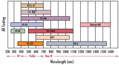
Figure 4: Wavelength Selection Diagram
λ/4 MgF2: The simplest AR coating available is a λ/4-thick MgF2 layer centered at 550nm (with refractive index of 1.38 at 550nm). MgF2 coating is ideal for broadband applications, though its performance varies depending on the glass substrate type.
VIS 0° and VIS 45°: The VIS 0° (for 0° angle of incidence) and VIS 45° (for 45° angle of incidence) coatings provide optimal transmission across 425-675nm, reducing average reflectance to 0.4% and 0.75% respectively. For visible light applications, VIS 0° AR coating outperforms MgF2.
VIS-NIR: This visible/near-infrared broadband AR coating is specially optimized to achieve maximum transmission (>99%) in the NIR region.
Telecom-NIR: A specialized broadband AR coating designed for popular telecom wavelengths between 1200-1600nm.
UV-AR and UV-VIS: These ultraviolet coatings are applied to our UV fused silica lenses and windows to enhance their performance in the UV spectrum.
NIR I and NIR II: The near-infrared I and II broadband AR coatings deliver exceptional performance at NIR wavelengths for fiber optics, laser diode modules, and LED lighting applications.
(Note: This translation maintains all technical specifications including wavelength ranges, reflectance values, and material properties. The text follows standard optical coating terminology while presenting the information in clear, structured paragraphs. All numerical values and units are preserved in their original format.)

_spectrum.png)
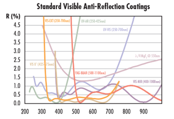
Figure 5: Standard AR coatings for the visible spectrum Figure 6: Standard AR coatings for the near-infrared (NIR) spectrum
_Coatings_for_the_Infrared_(IR)_Spectrum.png)
Figure 7: Standard Anti-Reflection (AR) Coatings for the Infrared (IR) Spectrum
| Coating Description | Specifications |
| lambda/4 MgF₂@550nm | R_≤1.75%@400-700nm |
| UV-AR [250-425nm] | R。≤1.0%@250-425nm R..≤0.75%@250-425nm R..≤0.5%@370-420nm |
| Laser UV-VIS [250-532nm] UV-VIS[250-700nm] | R_≤1.25%@250-532nm R_≤1.0% @350-450nm R_≤1.5%@250-700nm |
| VIS-EXT[350-700nm] | R_<0.5%@350-700nm |
| VIS-NIR[400-1000nm] | RA≤0.25%@880nm R_≤1.25%@400-870nm R_≤1.25%②890-1000nm |
| Laser VIS-NIR[500-1090nm] | R_≤1%@500-1090nm |
| VIS0°[425-675mm] VIS 45°[425-675nm] | R_≤0.4%@425-675nm R_≤0.75%@425-675mm |
| YAG-BBAR [500-1100mm] | RA<0.25%@532nm R。<0.25%@1064mm R_<1.0%@ 500-1100nm |
| NIRI[600-1050nm] | R_≤0.5%@600-1050nm |
| NIR Ⅱ[750-1550nm] | R_≤1.5%@750-800nm R_≤1.0%@800-1550nm R_≤0.7%@750-1550mm |
| Laser NIR[1030-1550nm] | R_≤0.7%@1030-1550nm |
| 2μm BBAR [1900-2100mm] | R.<0.5%@1900nm-2100nm R_<0.25%@2000nm-2100nm |
| BBAR(3000-5000nm) BBAR(3000-12000nm) BBAR(8000-12000nm) | R_<3.0%@3000-5000nm R。<3.0%@3000-12000nm R_<3.0%②8000-12000nm |
Standard BBAR Coating Reflectance Specifications