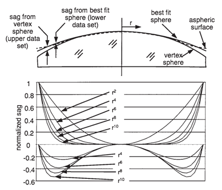
The correct use of aspheric surfaces is crucial, including decisions on which surface to make aspheric and whether to use conic sections or higher order aspheric. Conic sections include parabolic, hyperbolic, and ellipsoidal surfaces. The higher-order terms of an aspheric surface represent deviations from a conic section and are proportional to r4, r6, r8, etc., where r is the radial coordinate perpendicular to the optical axis.

In Figure 1, the upper part shows the sag of an aspheric surface compared to a vertex sphere and the sag of an aspheric surface compared to the best-fit sphere. The lower part of Figure 1 shows their specific normalized distances from the optical axis. From Figure 1, we can consider which surfaces in an optical system should be designed as aspheric and what shape these aspheric surfaces should take.
To begin, calculate the optical path difference (OPD) curve for a vertex spherical optical system. The aspheric surface from China aspheric lenses manufacturers can then be designed to match the basic shape of these data. For example, if the on-axis OPD plot resembles the r^6 term of the best-fit sphere’s sag, it may be beneficial to adjust the r^6 term coefficient of the surface near the aperture stop. If the off-axis OPD increases or decreases sharply at the edge of the pupil, adjusting one or two higher-order terms on a surface far from the stop may be beneficial.
Some considerations for aspheric surfaces are as follows:
Conic sections can be used to correct third-order spherical aberration and other lower-order aberrations.
If the surface is nearly flat, use polynomial terms and higher-order terms rather than the conic constant.
If the surface is at least slightly curved, the conic constant term can be used, along with higher-order terms if necessary.
It is best not to use the conic constant and the r^4 term simultaneously, as they are mathematically very similar; the first term in the expansion of a conic section is the r^4 term. While both can be used on a surface, the optimization process often uses one and ignores the other, resulting in falsely large coefficients, which is detrimental to optimization convergence.
Start with lower-order terms when using aspheric and progress to higher-order terms as needed. Using conic sections makes testing easier. The need for additional terms can be judged based on the characteristics of the OPD.
Using a large number of aspheric, especially higher-order aspheric, is complex because they interact with each other. This means that when one surface takes on a specific aspheric shape or profile, its sphericity may increase, but its effect may be counteracted by adjacent surfaces. For example, if one of two closely positioned aspheric surfaces deviates significantly from a sphere, the adjacent aspheric surface is likely to counteract this effect. Although the lens may theoretically be excellent, manufacturing two highly precise aspheric surfaces is a difficult, expensive, and possibly unnecessary task.
If possible, first optimize the design using spherical surfaces, then use the conic constant and/or aspheric coefficients in the final optimization stage. This helps keep the asphericity at a more controllable level.
It is worth reiterating that aspherics based on even-power polynomial series are widely used due to their simple expressions. In practical optical design, to achieve more design freedom, more even terms can be added to the polynomial expansion and optimized. In principle, as long as the number of polynomial terms is sufficient, this expression can approximate any rotationally symmetric aspheric surface to any desired accuracy. However, since the additional polynomial terms have no physical significance and are not orthogonal polynomials, the coefficients are often numerically unstable during optimization, often alternating in sign. For aspherics based on even-power polynomial series, the same aspheric surface shape may correspond to several sets of coefficients with different values and signs, thus representing the required aspheric shape through mutual cancellation of the coefficients. This mutual cancellation of additional polynomial coefficients can lead to reduced design efficiency, making it difficult for designers to control the aspheric shape by directly modifying the coefficients. It also increases the likelihood of rounding errors in the coefficients, reducing manufacturing and measurement efficiency.
ZEMAX provides an effective tool called the “Find Best Asphere Tool,” which helps automatically identify the most suitable surface to be made aspheric and optimizes the aspheric coefficients. Users can use this tool multiple times, each time changing the degrees of freedom of the aspherical lenses surface, to determine whether to keep or discard the ZEMAX-recommended aspheric surface.

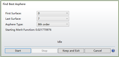
Figure 2 shows that this tool allows us to set the starting and ending surfaces and choose the maximum order of the polynomial. Each surface within the selected range is evaluated to see if it is the most suitable for an aspheric surface. Note that the selected surfaces must be standard surfaces (Standard), without a Conic value, defining the air-glass boundary conditions (cemented surfaces are usually not suitable for aspherics), and have a curvature as a variable or defined by the edge ray angle/F-number. Surfaces that do not meet these conditions are automatically ignored by ZEMAX. Once the selectable surfaces are determined, ZEMAX automatically defaults the most suitable surface to an aspheric type. The aspheric terms are set as variables for optimization. Local DLS optimization is used to improve system performance. If the system produces a lower merit function after optimizing this surface, it is retained. This process is repeated until all surfaces are tested. Finally, the tool reports which surface is most suitable for conversion to an aspheric surface with the lowest merit function.

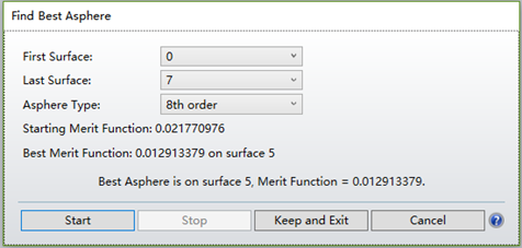
Figure 3 shows an example where setting the 5th surface as an aspheric surface results in the lowest merit function value. By clicking “Keep and Exit,” the 5th surface is automatically generated as an aspheric surface (Even Asphere). Note that when running this tool, the current merit function is used, and all parameters set as variables are re-optimized. Since local optimization is used, once optimization stops and a design with the minimum merit function is found, ZEMAX cannot know if a better design exists. Therefore, it is advisable to use the Hammer optimization at the end to see if there are any better solutions.